VTP(VLAN trunking protocol)
Used to dynamically add, remove and update VLANs(2-1000) Not really used much anymore. Its a Cisco proprietary protocol. I had a jr engineer that I worked with that was pretty close to implementing VTP at one time. I guess if his configs were valid we should have let him go through with it.
One other thing to add, is that this is not a trunking protocol such as ISL or 802.1Q. What we are doing with VTP is creating vlan's in once place and letting them replicate to other devices.
So now onto VTP
VTP packets are sent in the frames of ISL, and 802.1Q message, and it contains the following information.
- VTP version 1,2 or 3
Summary Advertisement
Subset Advertisement
Advertisement Request
VTP Join Message
Management Domain Length
Management Domain Name
VTP also has a configuration revision number which let shows the which revision
VTP is currently on, this is important as we will soon discover. When a switch receives a revision that is higher than its own it will act on it.
3 modes
-Server
-Client
-Default
Server
The default mode. This is the one that can change VLANS, Sends and receives VTP updates.(2-1000) are configurable
Client
Takes orders from the server.
Sends and receive updates
Transparent(recommended mode)
Can change Vlan info
Just passes through Vlan configs to other switches
Does not act on VLAN advertisements
always at revision 0
The switches need to be in transparent mode to configure extended Vlans (1006-4096)
Authentication
Domain names and passwords can be setup to allow for protection throughout your network. Make sure you have a separate name for Lab and Production switches, as this will cause some pain later on.
VTP pruning.
Allows you to get rid of vlans that arent' needed. You can only do this with vlan 2-1000, and done from a VTP server
One think I forgot to mention is that devices need to be setup as trunks for VTP work to work, I just wanted to make sure I mentioned that before you get carried away.
Friday, April 29, 2011
Thursday, April 28, 2011
How many Static routes are too many
Recently in my new position I have started to work in the small medium business arena. One of the biggest challenges in coming from the enterprise environment is the lack of routing protocols. Some of it is due to knowledge of the internal IT staff, some of it is due to the VAR's that provide service, and other times its politics. This shouldn't seem like a big deal, but I get a few calls every week of something that isn't reachable in some way shape or form. 99 percent of the time when the routing was updated someone forgot to save the changes then "power" happens and routes are lost. This customer in particular has 3 sites over MPLS VPN, and a few more sites that come in site to site VPN's over ASA's. When I pull the configs for the devices I see pages of static routes to get to locations. I have asked them several times why don't they run OSPF or EIGRP, and they always say "we like things with static routes". Well if you like them you shouldn't call me ever few weeks cause you can't get somewhere. So how do we fix these problems. We usually just go right up the OSI model. Start with the device that can't talk to the far end, trace route to where it gets suck and check the control and data plane's on that device. All and all this doesn't seem to be a big deal, but at times it can take hours when firewalls, and DMZ's and undocumented configs are into play. This brings me back to my point OSPF, EIGRP will detect link failure quickly and the packets will either find a way or if syslog is setup correctly we will get alerts of link failure. This is just another rant of the day in the life of a network engineer.
Sunday, April 10, 2011
VLANS
VLAN's
What are VLAN's
Vlan's are virtual Local Area Networks. The idea here is to break up BCST domains into smaller chunks. Host in the same vlan can communicate with each other, but will have to be routed to get outside the vlan due to the ARP protocol being a BCST which is stopped at the layer 3 boundary.
Vlans should be defined by physical location. Like a switch closet should contain different vlans from other switching closets.
Vlans are a number that the switch uses with a port. 12 Bits 0-4095
Normal VLAN's 1-1005
1 Default Vlan Ports default here. Should move them to another non routed vlan for security reasons.
1002/4 Default FDDI vlans
1003/5 Default Token Rings
Extended Vlans 1006-4094
Once a vlan is created the switch or device will make a Cam table for that individual vlan. Also a spanning tree instance is created. Ports can be one of 3 things when working at the layer 2 level.
- Access
- Trunk
- Dynamic
Access - Where PC, Phones and printers plug in.
Trunks - Where Multiple Vlans can come through these ports usually used when leaving the device and going to the next devices
Dynamic - Automatically chooses port type
More on trunks:
Trunk Links are used when we want to have our vlans go between switches or routers. To do this we have to TAG the packets when they leave the device. We will add ISL(cisco prop) or 802.1Q(IEEE).
802.1Q has a 4 byte tag between the source and destination MAC and the Lenth/ethertype fields(check the pic below). The frame is modified for .1Q except for the native vlan. we don't usually see to much with ISL. Both sides of the link have to be the same, but they are local to the device.
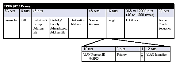
FCS is also modified since we had changed the frame.
Native Vlan
Normal traffic will be sent untagged across the native Vlan. This is usually Vlan 1 in most devices.
QinQ support
we can have vlans stacked on top of each other on each frame. Sometimes known as Metro Tagging when used with Metro E environments.
Stay tuned for more later on...
What are VLAN's
Vlan's are virtual Local Area Networks. The idea here is to break up BCST domains into smaller chunks. Host in the same vlan can communicate with each other, but will have to be routed to get outside the vlan due to the ARP protocol being a BCST which is stopped at the layer 3 boundary.
Vlans should be defined by physical location. Like a switch closet should contain different vlans from other switching closets.
Vlans are a number that the switch uses with a port. 12 Bits 0-4095
Normal VLAN's 1-1005
1 Default Vlan Ports default here. Should move them to another non routed vlan for security reasons.
1002/4 Default FDDI vlans
1003/5 Default Token Rings
Extended Vlans 1006-4094
Once a vlan is created the switch or device will make a Cam table for that individual vlan. Also a spanning tree instance is created. Ports can be one of 3 things when working at the layer 2 level.
- Access
- Trunk
- Dynamic
Access - Where PC, Phones and printers plug in.
Trunks - Where Multiple Vlans can come through these ports usually used when leaving the device and going to the next devices
Dynamic - Automatically chooses port type
More on trunks:
Trunk Links are used when we want to have our vlans go between switches or routers. To do this we have to TAG the packets when they leave the device. We will add ISL(cisco prop) or 802.1Q(IEEE).
802.1Q has a 4 byte tag between the source and destination MAC and the Lenth/ethertype fields(check the pic below). The frame is modified for .1Q except for the native vlan. we don't usually see to much with ISL. Both sides of the link have to be the same, but they are local to the device.
FCS is also modified since we had changed the frame.
Native Vlan
Normal traffic will be sent untagged across the native Vlan. This is usually Vlan 1 in most devices.
QinQ support
we can have vlans stacked on top of each other on each frame. Sometimes known as Metro Tagging when used with Metro E environments.
Stay tuned for more later on...
Monday, April 4, 2011
Campus Network Design
Most campus networks have a 3 Tier setup with 3 distinct layers
Access Layer
Where user connect and we have ports that belong to certain VLAN's. Not much routing done here. So here we can have PC's, Printers, VOIP phones. This is where we see our 2960 switches located. We have multiple uplinks to distro switches. QOS is applied here, we can have Port Security here.
Distribution layer
This is where the layer 3 switches are located. The Access switches will meet up here and there are uplinks to the Core Switches. We also Run HSRP/VRRP/GLBP here. Etherchannel is also ran here. This is also where we would summarize addresses to make the routing table smaller.
Core Layer
The most powerful devices and we usually like to have little policy here we like to forward packets as fast as possible. Usually no access list or QOS.
Stay Tuned for more.
We use those building blocks cause its easy to replicate and expand on if we need changes. Blocks can be added or removed with Ease. T/S is also easier as we can isolate faults in individual blocks.
Change in Direction
I have to get a few certs for the job, so I'm going to be not doing as much VOIP unless I get some crazy issue that comes in that just needs addressing. I will be getting some specialist certs for the job that focus on route/switch, so I will be posting about those topics. I do have my CCNP, but I'm starting fresh from ground zero and working my way back up to fill in holes and see what I learned new when going over basic material. From there we will go into Layer 2 topics such as STP, etherchannels, and Vlans, and then move onto layer 3 topics such as OSPF, EIGRP, BGP,MPLS, and then add on some trimmings such as IPV6, Multicast and WAAS. Stay Tuned.
Sunday, April 3, 2011
Dial-Peers
Its that time. dial-Peers are one of the most important parts of your VOIP network.
2 types of Dial Peers
POTS- THey usually point to the PSTN or a FXO/FXS port.
Voice- These can point to a call manager, Gatekeeper, another voice gateway.
In most networks your going to have at least a few call legs and you are going to have dial peers on each of those legs. As an example.

Now the key part is that there has to be something that matches when it comes to inbound and outbound dial-peers and it can get a little tricky with the logic on how inbound and outbound dial-peers work.
Inbound dial-peer:
When you get a call from the PSTN from a ISDN line or a FXO port there is going to be a dial-peer that it matches. Its usually going to look something like
dial-peer voice 1 pots
incoming called-number .
direct-inward-dial
port 0/0/0:23
We have the dial-peer the number(tag) can be anything and we have it as a pots dial peer. The next part we have incoming call number with a "." to match anything. We have direct-inward-dial so we don't get another dial tone(i'll get to that in part 2) and we have the port that it comes in on. So when the call comes we are matching anything so it doesn't have to go down the list of options. If we didn't it would match:
1. Called Number/DNIS Incoming called-number(command)which we are using
2. Calling number/ANI Answer-Address(command) we can use this kinda like a route map where we can have "policy based calling"
3. Calling number with Destination-Pattern command
4. Voice port (bad choice)
5. Default dial-peer 0 (even worse choice)
So once thats taken care of we have matched the 1st call leg. Now we need a outbound dial-peer to send the call on its way.
So an outbound dial-peer will look something like:
dial-peer voice 2 voip
destination-pattern [347]..
session target ipv4:192.168.100.10
So the outbound portion is not as complex as the inbound. As you can see we have a voip dial-peer a destination-pattern where we are looking for a 3,4, or 7 and any other 3 digits and we the session target ipv4 command pointing to another IP address which can be another router, call manager and so on. If we are sending the call to call manager, call manager will start its process of routing the call, to the correct endpoint and if we are going to another router we are starting this process all over again until we reach our destination. This is a pretty high level overview. I didn't touch of overlapping digits, DID, and a few other commands you can add onto dial-peers to get more control out of them. Look for that in an upcoming topic.
2 types of Dial Peers
POTS- THey usually point to the PSTN or a FXO/FXS port.
Voice- These can point to a call manager, Gatekeeper, another voice gateway.
In most networks your going to have at least a few call legs and you are going to have dial peers on each of those legs. As an example.
Now the key part is that there has to be something that matches when it comes to inbound and outbound dial-peers and it can get a little tricky with the logic on how inbound and outbound dial-peers work.
Inbound dial-peer:
When you get a call from the PSTN from a ISDN line or a FXO port there is going to be a dial-peer that it matches. Its usually going to look something like
dial-peer voice 1 pots
incoming called-number .
direct-inward-dial
port 0/0/0:23
We have the dial-peer the number(tag) can be anything and we have it as a pots dial peer. The next part we have incoming call number with a "." to match anything. We have direct-inward-dial so we don't get another dial tone(i'll get to that in part 2) and we have the port that it comes in on. So when the call comes we are matching anything so it doesn't have to go down the list of options. If we didn't it would match:
1. Called Number/DNIS Incoming called-number(command)which we are using
2. Calling number/ANI Answer-Address(command) we can use this kinda like a route map where we can have "policy based calling"
3. Calling number with Destination-Pattern command
4. Voice port (bad choice)
5. Default dial-peer 0 (even worse choice)
So once thats taken care of we have matched the 1st call leg. Now we need a outbound dial-peer to send the call on its way.
So an outbound dial-peer will look something like:
dial-peer voice 2 voip
destination-pattern [347]..
session target ipv4:192.168.100.10
So the outbound portion is not as complex as the inbound. As you can see we have a voip dial-peer a destination-pattern where we are looking for a 3,4, or 7 and any other 3 digits and we the session target ipv4 command pointing to another IP address which can be another router, call manager and so on. If we are sending the call to call manager, call manager will start its process of routing the call, to the correct endpoint and if we are going to another router we are starting this process all over again until we reach our destination. This is a pretty high level overview. I didn't touch of overlapping digits, DID, and a few other commands you can add onto dial-peers to get more control out of them. Look for that in an upcoming topic.
Subscribe to:
Posts (Atom)